
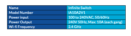
Specifications

2.4 GHz
Wi-fi Frequency
100 to 240VAC, 50/60Hz
Power Input
Dual Output
Power Output
89 x 70 x 26 mm
Dimensions
Switch

Infinite Switch
Important safety information
Please read this and other device guides carefully. The failure to follow the recommendations set forth by Infinite Automation can be dangerous or cause a violation of the law. The manufacturer, distributor, and/ or reseller will not be held responsible for any loss or damage resulting from not following any instructions in this guide or in other materials.
Install the Infinite Switch
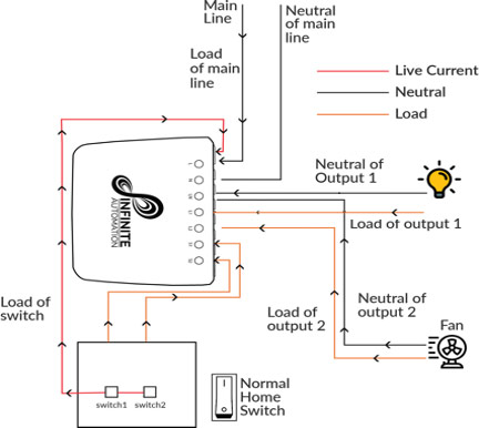
Infinite Switch installs behind a power switch or a push-button switch. Infinite switch setup is very simple. It works with only 3-wire (with neutral). Please follow the steps below:
- Shut off the main circuit breaker of your home for safety during the installation and ensure the wires are not short circuited during the installation which will cause damage to the Infinite Switch
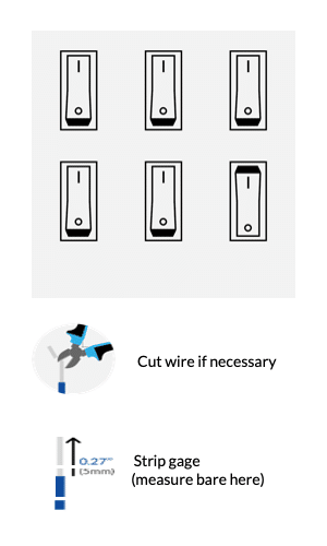
- Preparing connection wires. Use the wire stripper cut the metallic part of the connection wire and make sure the length of the metallic part is about 5mm. Strip the cord sheath and insulation and prepare flex cord as required for installation. Slip the bushing over the flex cord
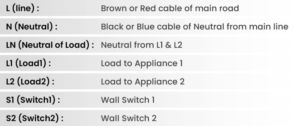
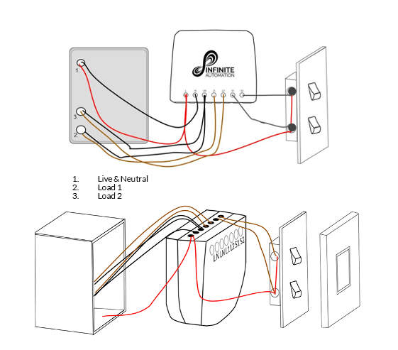
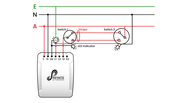
Installation Diagram – Infinite Switch
- Loose the terminal screws and ensure adequate space to insert cord conductor
- Connect wires correctly as per shown in diagram above and double check all the connection carefully
- Make sure bare wires are fully inserted into the terminal & there are no loose strands of wire.
- Wires and terminals must be tightened adequately as per Australian standards, rules and regulations to make sure wire doesn’t come out after installation.
- Make sure all the conductors are tightened by terminal screws properly.
- Make sure neutrals are connected. N & LN must not loop anywhere and connected as shown in diagram above to make power consumption work correctly.
Gang box Installation
Gang box is used in case of non-insulated or surface mounting conditions. Please follow guide below for cabling. It is same as installation diagram above.
Steps to install gangbox
- Connect all cables as per cabling guide to switch connectors. Place the Switch inside the gang box towards the back of the box.
- Position the cables towards the back of the box.
- Reinstall the Switch to the gang box.
- Reinstall the cover onto the gang box.
Restore Power
Restore power at the circuit breaker or fuse
Technical Information
The device is compatible to max currents for each gang as per below:
Output: 240VAC 50/60Hz
Load Max: 10A
Max standby power: <0.7W
Power measurement accuracy: + or – 3W
Dimensions: 89 x 70 x 26 mm
Accepted Input for L: 100 – 240VAC, 50/60Hz
External Switch Voltage Requirements:
L and N inputted with 100 – 240VAC, then the external switch also be powered by 100 – 240VAC to
S1 or S2 connection.
Environment of Installation:
Must be installed indoors or weatherproof box in outdoor areas
Should be located in a dry location
Surface mount should be installed in a fire resistant plastic box.
Compatible wiring size for our connectors: 12AWG – 26AWG.
Factory Reset: 7 consecutive on and off from wall switch will reset the hardware.
2 way switches with LED indicator: Do not wire LED indicator across wall switches terminals 1 & 2. This works with conventional wiring. Installing this way with our device will cause S1 (or S2) to switch on and off rapidly which will reset device. Please refer to diagram for 2way switch with LED Indicator below.
Notes:
- All the installation work must be performed by qualified electrician.
- Smart switch installs behind a lighting switch or a momentary push button switch. If switch needs installation in Roof or non-insulated environment. Electrician must use junction box. Switch must be installed as per standard guidelines and requirements Specifications can be modified without notice due to continuous improvement.